I have to thank Con, DF4SA, of Spiderbeam for giving me the opportunity to inexpensively try their new
18m telescoping pole. I turned it into a great 160m through 30m antenna; as a bonus it makes a good tree surrogate to hang a 15m dipole from.

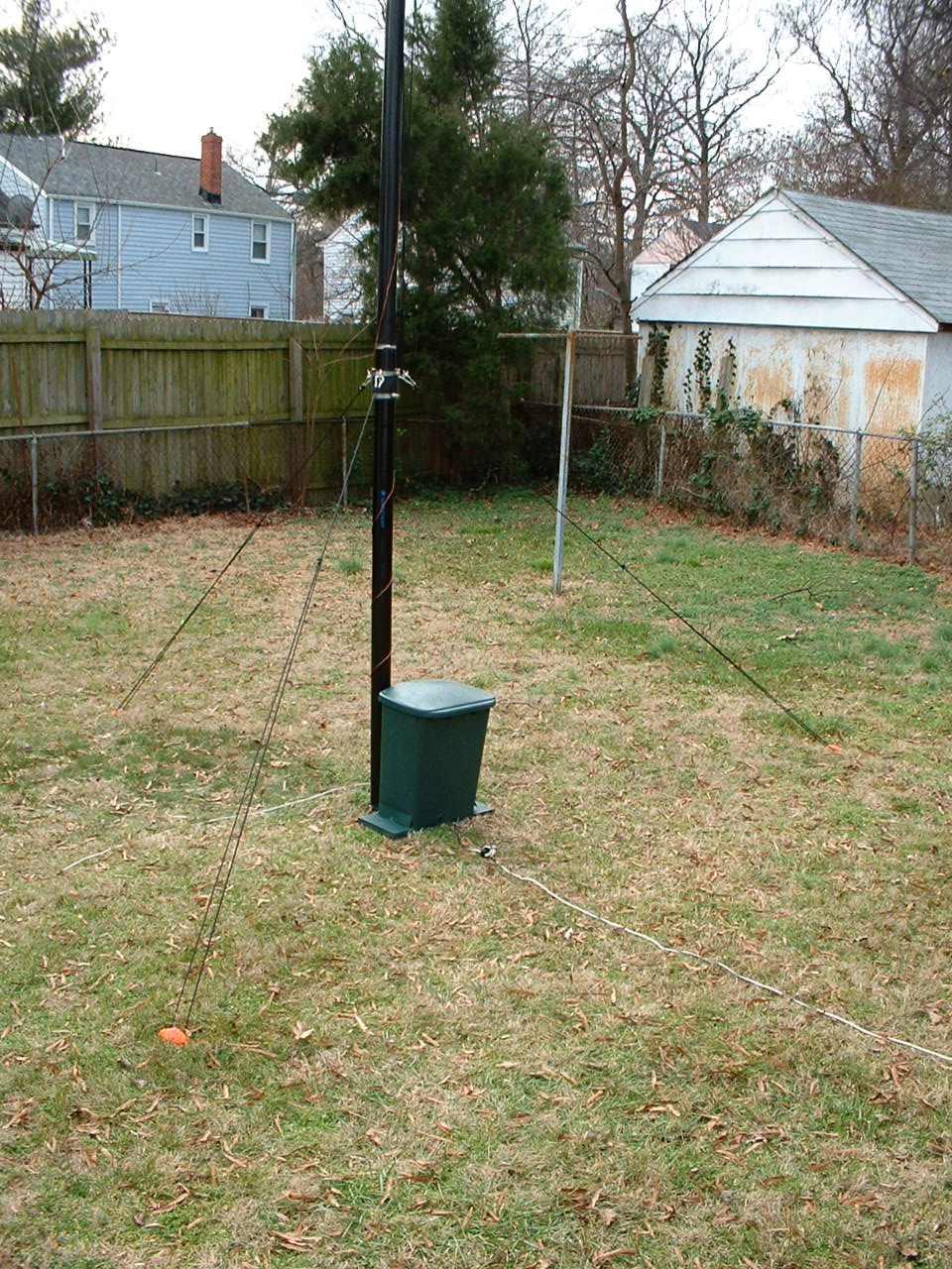
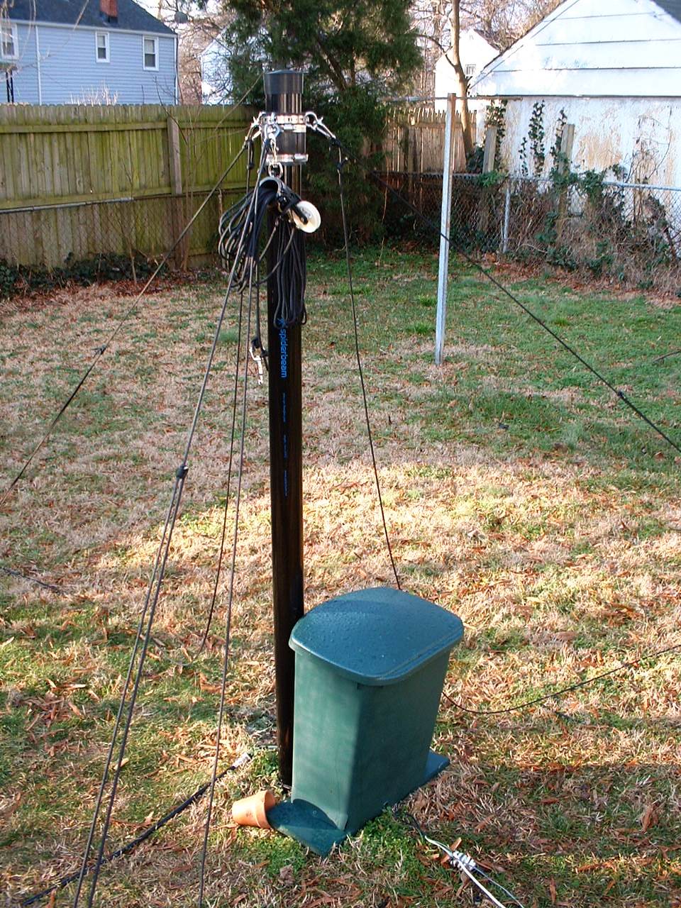
Up from the base of the sixty footer. I needed two sets of guys on this one.
The antenna is just the bigger brother of the
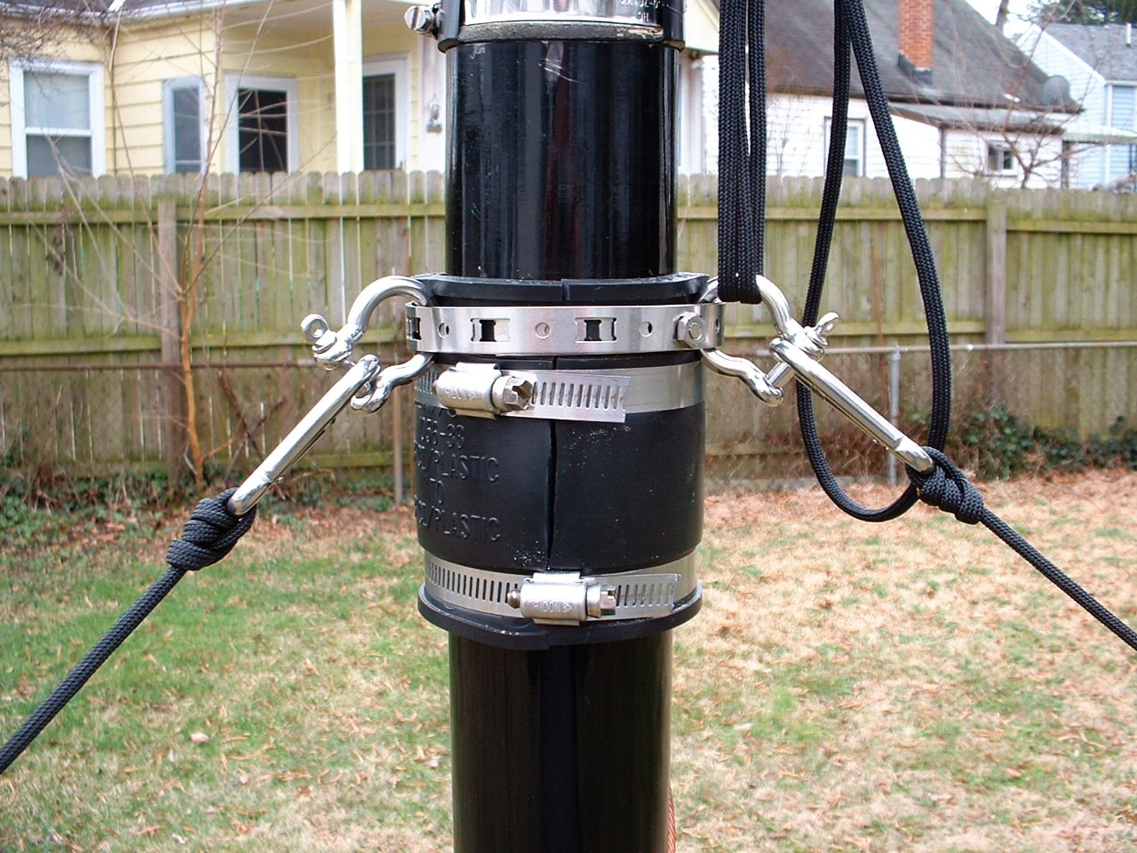
40 foot pole vertical and I took essentially the same approach to this antenna, but had a chance to make some improvements. This antenna ended up being a little more mechanically complicated, because guying the bottom section only just seemed much too floppy. I elected to put a second set of guys at the twenty-five foot level, which seems to be sufficient for 25MPH or so winds. It hasn't been through a major windstorm yet, and I'd probably prefer not to find out what happens. I may add a third set of very light monofilament guys very close to the top to cut down the sway, but we'll see. The guys on this antenna are attached using hardware you can find at your local home improvement store. I used flexible drain pipe couplings as nice guy attachment points.

A strap is wrapped several times around the shackles and held with a small bolt and nut.
The original bottom guy attachment ring had the three stainless steel shackles threaded onto the top hose clamp before assembly. It can be seen on other pictures on this page. Lee, W9OY, has pointed out that this very well might be asking for trouble, because the screw might slip on the clamp and the bottom guys would be lost. I've since significantly reinforced the attachment of the shackles with a bolted stainless steel strap.
Snap links are used at the ends of the black 3/16" Dacron bottom guys for easy detachment if I want to take the whole thing inside (or to Field Day!) The rubber protects the pole surface from damage. The upper guy attachment ring (another flex drain coupling) is very similar, except that there are three snap hooks attached to it to clip onto bowline knots at the end of each of the top ropes. Up top, I used 3/16" black Dacron because it was what I had on hand. Smaller rope could have been used, but the only small twine I had was white nylon, and I felt that the black guys were much more attractive. All guy anchor points are 16" tent stakes driven into the lawn. The bottom guys come down 7' from the antenna base and the top guys come down 14' from the base.
With the guy ropes attached, there's a significant downward load on all of the sections below the upper guy ring, so I made use of the Spiderbeam supplied stainless steel clamps on the sections below the upper guy attachment. I originally left them off above it because it takes significantly longer to put this antenna up because of all the extra ropes and clamps to deal with, but I had an incident in 25MPH wind where the top half of the antenna fell down into the bottom half. A thirty foot fall is no joke, and I was merely lucky that there wasn't any damage, so now I'm going to take the extra few minutes to put the clamps on all the way up.

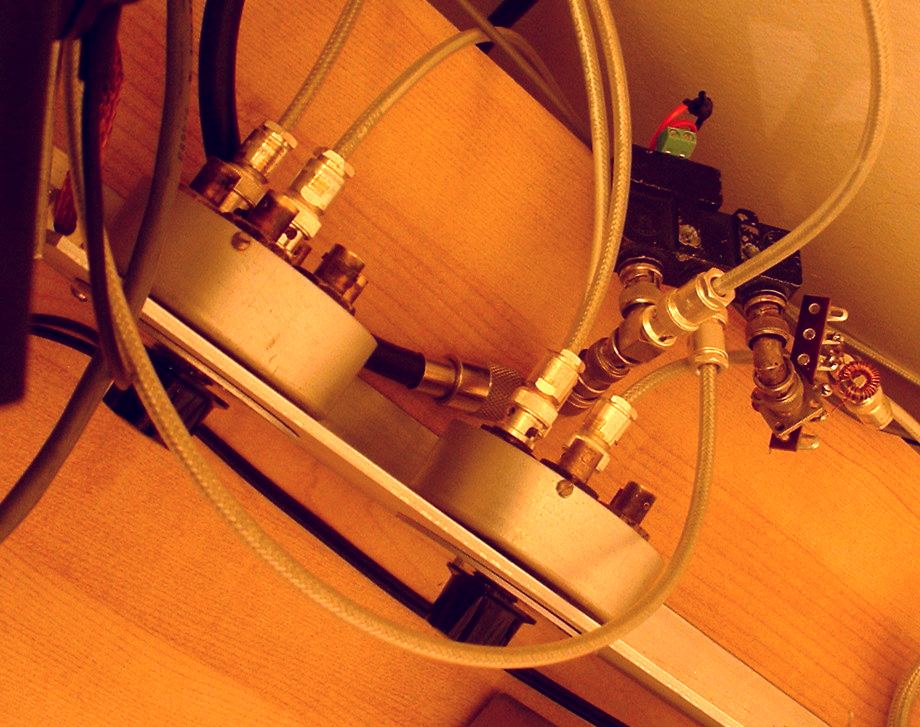
A painted and hacked up garbage can houses the matching networks.
The antenna is naturally resonant around 3.6MHz, but I wanted to use it on 160m, 80m/75m, 40m, and 30m. I didn't add 60m matching because I found I don't really use the channels there. This antenna is slightly more than 5/8ths wavelength long on 30m, and so the antenna is not particularly good on bands above 30, but that's no hindrance here. The matching networks all fit into the top three-quarters of a kitchen-size garbage can which I mounted to a wooden board. I painted the whole thing with textured green spray paint for plastics so I didn't have a stupid shiny white garbage can in the backyard. If I had been in less of a hurry to put the antenna together, I might have built another house-like matching box, just because it's cuter, but the painted can isn't unacceptably ugly.
I added some extra radials as I was putting this antenna together. The radial system consists now of the original 27 radials out to the edges of the 40' x 40' backyard, as well as about ten new ones that extend to the front yard around the house, each about 85' - 90' long. I wanted to collect a little more ground current on 160m. I haven't done an A/B test with the new vertical and the new radials to see if they make a real difference, but the new additions probably result in almost twice the area covered with radials with less than 0.02λ between tips. Consider the fact that I'm using a very small ground system if you try to duplicate the matching networks below. My tap points, especially on 160m, probably will be significantly altered if you have a good ground system. I've used all the space I've got.

The matching mess... a thing of beauty.
I used a hodgepodge of matching networks on this antenna, just as I did on the forty foot one. I hand wound all inductors, some of them on lathed forms. Matching network electrical details can be found here:
matching_networks_18m.pdf
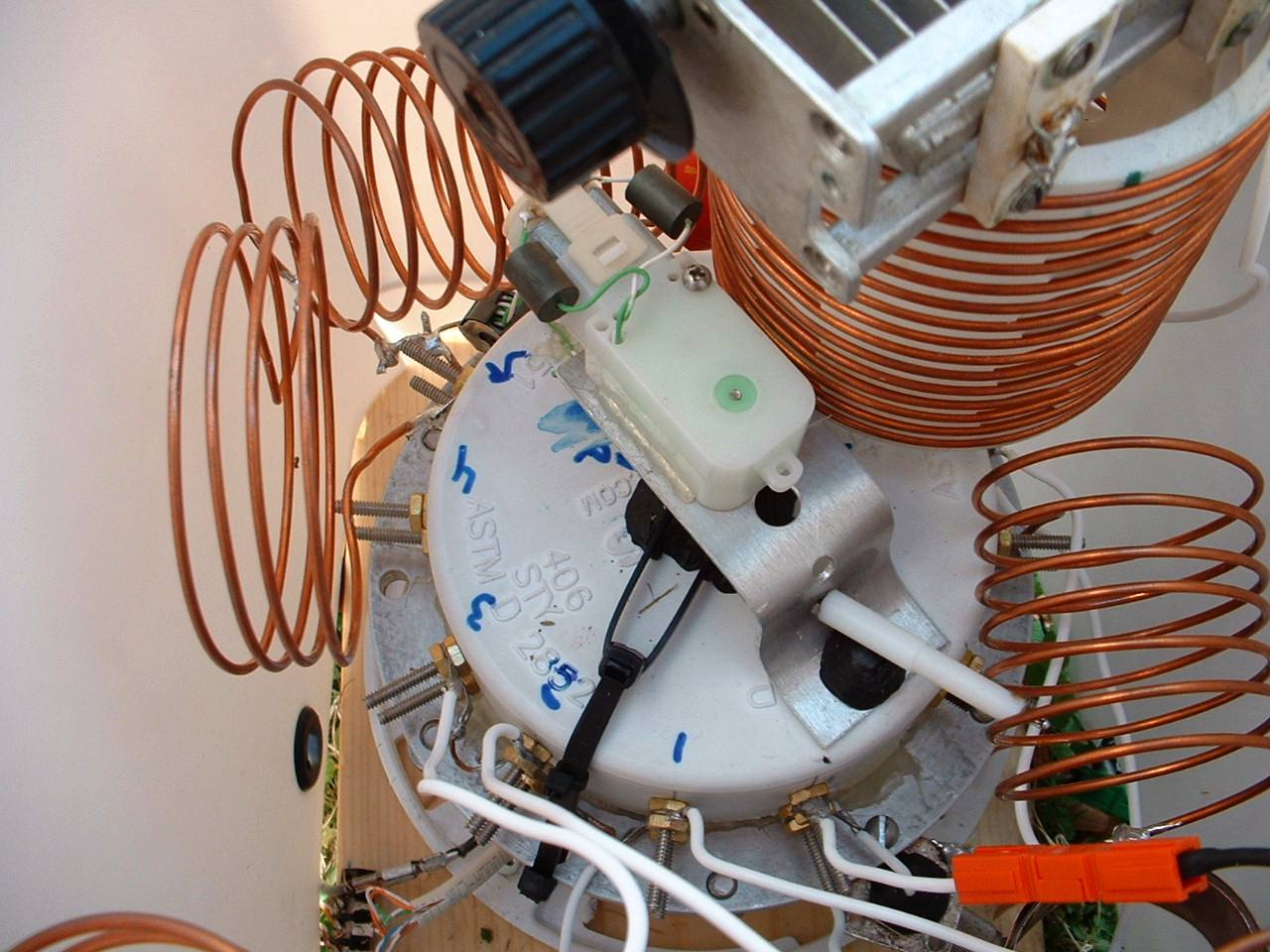
The networks are switched by a motorized wafer switch just like the one on the other antenna, except that I wanted a mechanically more rugged switch arrangement, because the contacts on the 40-foot matching switch were stressed a little too much by the wires attached to the switch. The resulting switch is pictured below

The ruggedized bandswitch managed to get itself dubbed "the moonlander".
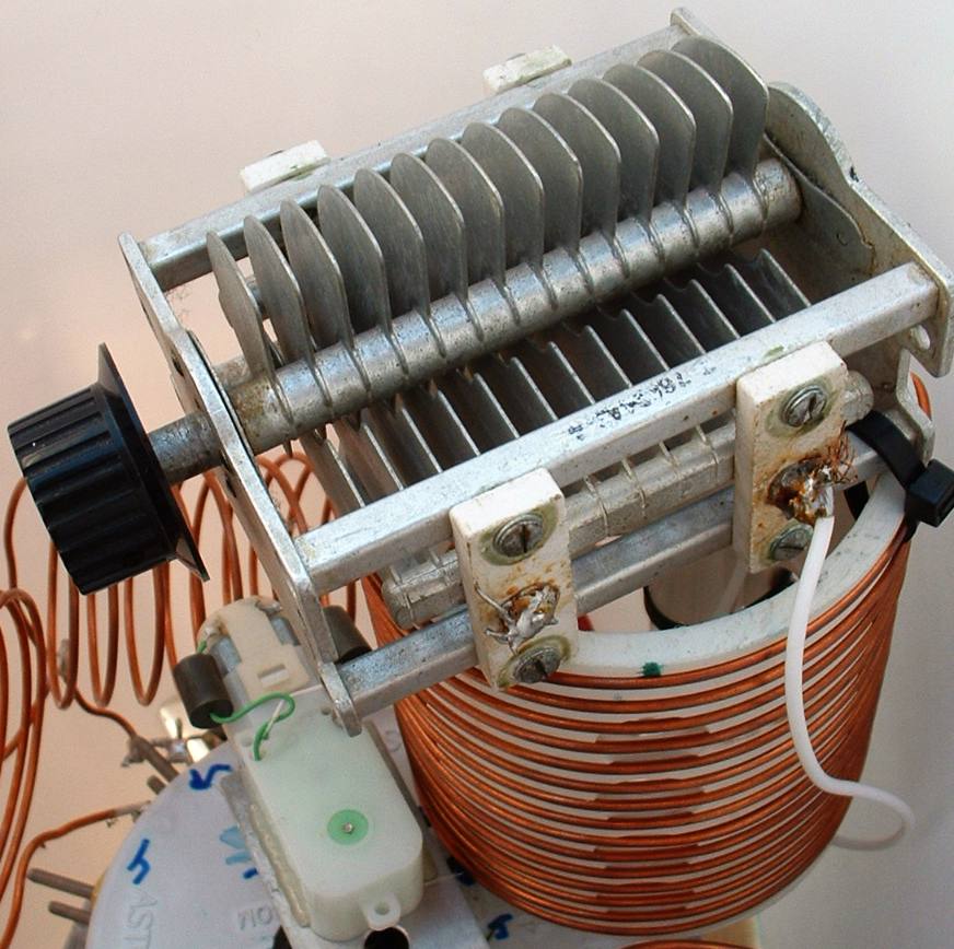
The wafer switch is mounted in the center of a polystyrene drain pipe cap. Twelve pairs of #6 stainless machine screws and brass nuts stud the outer perimeter of the pipe cap, and each screw bolts a solder lug to the inside of the cap. Each switch contact is connected by a small piece of AWG 18 bare wire to its corresponding bolt. That way, all connections are made simply by clamping another solder lug to the outside and the bolts take all the stress. The wafer switch has two wafers and 12 positions. One wafer switches the antenna wire to all the "ant" ports on the matching networks. The other wafer switches the "tx" ports to the coax. All the matching shunt elements just go to the common ground point.
One switch position is hardwired inside the housing to be a bypass for general RX. There are four switch positions (1-4 in the photo) for 160m; three are currently hooked up. There are three positions to cover all of 80m, one position for 40m, one position for 30m, and a couple more unused ones that I intend on saving for matching a more efficent 160m antenna option, maybe an inverted L or T antenna with some top loading. As usual, I used
a servo controlled gearmotor to drive the switch. The feedback pot is hidden from view, coupled to the bottom of the switch. A drawing of the bandswitch arrangement is available here:
The aluminum piece below the moonlander provides a common ground point. I attached a copper buss wire around the perimeter (underneath the aluminum flange) with stainless hardware so I could solder things to ground.

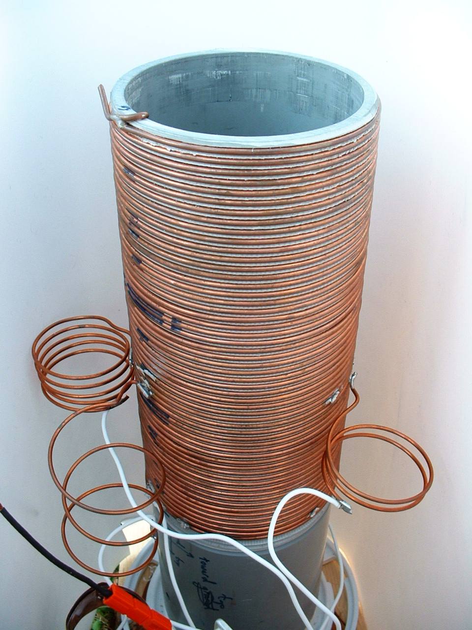
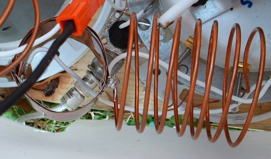
The 160m base loading and matching coil is about 25 turns of #10 wire 6TPI
The base loaded antenna on 160m only has about a 20kHz 2:1 SWR bandwidth per coil tap. I can cover the bottom 60kHz of the band at present and will probably make the fourth switch tap for 160m be up high in the phone band for keeping in contact with regional friends. The 160m coil is wound on a lathe-grooved piece of grey PVC electrical conduit and is MUCH larger than necessary. A drawback to this is that one turn is too much inductance to get slightly overlapping tap points, so I added some small 2" diameter inductors to fine-tune the resonances so I could cover all frequencies between 1.800 and 1.860. I may eventually go to a smaller, less tightly wound inductor. I was using about twice this inductance to base load the 40-footer as an experiment, and just had this coil, so I used it. This antenna is much better than the 40-footer on 160m. I measured this antenna as having a 6dB field strength improvement over the 40 foot one, more than expected.

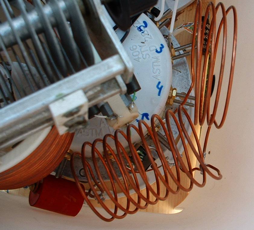
Three tap points and modest reactances cover all of 75/80m
Moving on to the 3.5-4.0MHz range, I found that I only needed three networks to cover the whole band. The first two taps both share a shunt inductor (about 10 turns, see the .pdf). The lowest tap has a small series inductor as well. The middle tap is simply a hairpin matching arrangement; that is, the antenna is slightly capacitive by itself and the shunt inductor steps the impedance up to 50 ohms. The highest 75m tap is a "capacitive hairpin" arrangement. The radiator is slightly inductive by itself, and a shunt 500pF doorknob capacitor steps the impedance up to 50 ohms. With these three switch positions, I can cover the whole band with quite low SWR.

The forty meter network needs a big coil, relatively.
The high base impedance of the 40m antenna required a big coil for its L network. (I think it's about 8μH as installed). The step down L-network uses a large shunt coil on a PVC form and a nice Hammarlund variable cap that I've had for years and never found particularly useful because it has a maximum capacitance of 120pF. I needed about 60pF for this L-network, though, and it was perfect. This network easily covers the whole band. The antenna used on 40m could potentially use a parallel-resonant circuit as well, but the L-network seems to work just fine. The impedance on 40m didn't agree entirely with the EZNEC model and I ended up having to take a couple of turns off of the coil to get midband resonance.

The thirty meter network with a homebrew capacitor.
On 30m, I found that I'd run out of capacitors and really only needed a very small one (50pF) and also knew that even if I eventually got an amp, I wouldn't need high voltage capabilities on 30m with the 200W power limitation, so I built my own. The capacitor uses copper foil for plates and some overhead transparency material (I think that stuff is polyester) for the dielectric. It seems to work fine. I found on 30m, again, that my EZNEC modeled impedance was significantly off from the real one. I had to reduce the shunt coil by several turns in order to find a match midband on 30m.

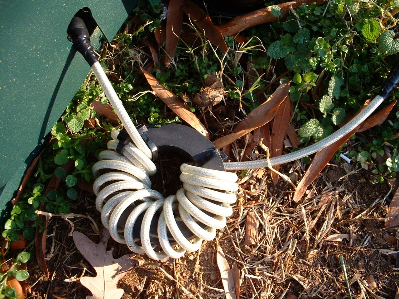
Rounding out the electrical details, there's a common mode choke at the feedpoint.
I added a choke at the feedpoint mainly because I've got a lot of noise around here. I'm going to try some more aggressive choking in the future, but it's a start. I never had any problems with RF in the shack with this antenna... not surprising with a ground mounted vertical and only 100W, maybe, but I worry about RF out of the shack here. This is a modest choke, maybe up to 1kΩ across 160-30m, but I can't really measure it. It's a decent guess based on winding a few turns on the thing and measuring with my MFJ-259B, but I didn't check a few turns over the whole range... I just swept and made sure the finished choke was |Z|>650Ω across a large swath of HF, and it is. I also choked the control lines for the moonlander, though they're mostly electrically isolated at the matching box end anyway. The motor frame is plastic and so is the pot frame, so the motor drive system is really only lightly coupled to the RF-energized parts.

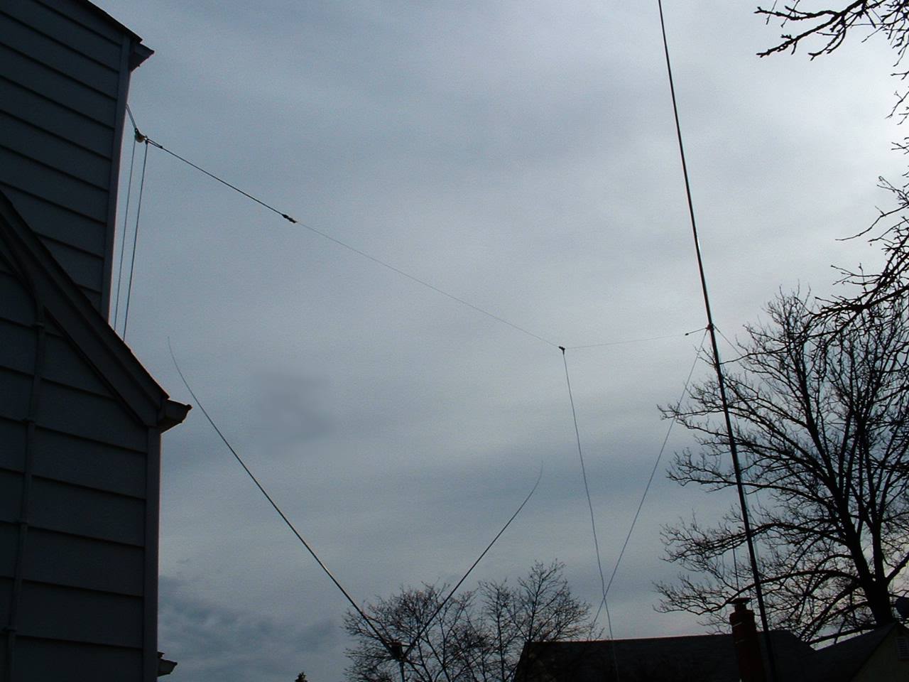
All of the HF antennas at N3OX.
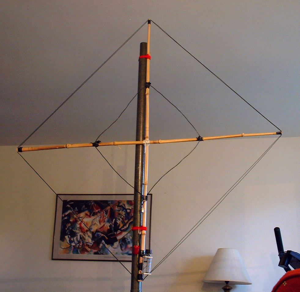
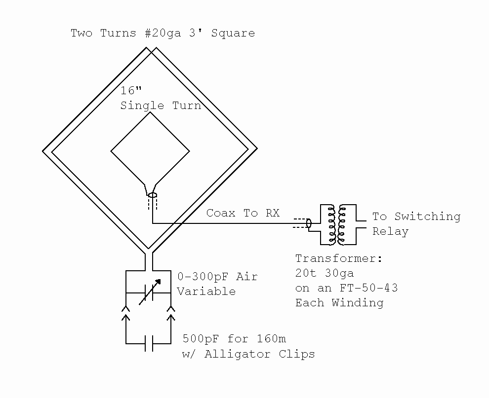
I'm plagued with a treeless backyard here, despite the fact that all my neighbors have nice tall trees. This is what got me started on all this fiberglass pole stuff anyway. I figured I'd make the best of being forced to guy this pole at thirty feet from the base, and I added a small plastic clothesline pulley at the top guy point and a dacron rope loop to hoist a 15m dipole between the pole and the house. A similar rope loop holds the house end of the dipole. I have a snap hook on either end so that I can easily drop and detach the dipole when I'm going to take down the 18m pole. The two fiberglass poles in a vee in the background are two sides of a fine-gauge 20m delta loop. The box at the bottom corner of the triangle houses L-networks to match the antenna on 17m and 20m. So, now I have capabilities on 160m, 80m, 40m, 30m, 20m, 17m, and 15m from my small lot here in DC suburbia.

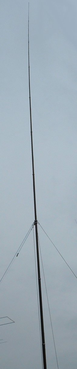
The antennas as seen from the street on the side of my house. As usual, the big pole has a sun-heated curve to it.
I've got to say I'm very happy with this antenna. The 160m improvement was shocking. I've at least got "if I can hear them I can work them" capabilities with this antenna, which makes it easy to have nice QSO's with the larger EU stations. On 80m and 40m, I've busted big pileups with 100W. I'm sure once I figure out some lowband RX antennas, this antenna won't be quite as impressive (as I won't be able to work everything I hear with only 100W) but right now I'm pretty excited to be putting out a pretty big signal on the lower bands.
I'd recommend this pole to anyone in my situation at this point in the sunspot cycle. The pole is inexpensive compared to other 60 foot vertical supports. It's temporary so it's good for renters or those in restricted situations, or those with difficult zoning and building code situations. It's still generally wieldy enough for one person to install and telescope up, though it's more difficult than the forty-footer because the sections are nearly as tall as I am.

I usually leave the pole standing when collapsed.
My best time to telescope it up, put on all the clamps and adjust the guys is about fifteen minutes in the dark. That's from the state in the picture above, add a few minutes if you really must take the thing inside when you're not using it. It's not invisible, but it's certainly fairly low profile visually and is completely invisible from afar at night. It's a little imposing when you're right under it during the day but it's not out of the question to only put it up in the dark. If you need some low-band help, it might just be the ticket.


